Creative Motion Control Course Documentation
Course project documentation
View the Project on GitHub Creative-Motion-Control-Course/Team-Project
Project 1: Modular Signal Plotter
Concept
This project is inspired by the fact that Stepdance itself was developed from ideas rooted in modular synthesis. Building on this connection, the project proposes a system that extends this relationship: instead of using modular synthesis to generate sound, it uses modular signals to generate motion. The plotter translates electrical signals from a modular system into movement, treating control voltage as a source of motion energy rather than sound. Inspired by modular patching, the same signal can take on different roles—such as oscillation, modulation, or accumulation—depending on how it is used within the system. Rather than visualizing sound directly, the project focuses on how signal structures can shape behavior, resulting in drawings that evolve through oscillation, variation, and repetition
Core Idea
One signal, multiple behaviors
- A single input signal (LFO or CV) is used
- The system reinterprets this signal in different ways
- Each interpretation produces a different drawing style
- The starting point, end point, length of the path, and the shape of the path.
- The starting point, the duration, the direction of movement at particular time of duration, the speed of the movement at particular time of the duration
The difference lies in whether we focus on delivering the final outcome on the paper, which makes a paint stroke a state invariant shape, or focus on the painting process of the plotter, make it more like a machine performance and have the paper painting only as a side profile of the process.
System Structure
System Structure
Implementation
1. Inputs
- Primary Input: Modular LFO (connected to A1)User control:
- Potentiometer → controls intensity (amplitude)
- Button → switches behavior modes
2. Signal Mapping
The same input signal is reused in different ways depending on mode:
Mode 1 — Oscillation
Signal controls vertical movement and produces smooth wave-like lines.
y = sin(t) × signal
Mode 2 — Distortion
Signal introduces irregular variation and produces unstable, noisy lines.
y = sin(t) + signal × noise
Mode 3 — Iterative Drift
Signal accumulates over time and produces gradually shifting structures.
state = state + signal × small_factor
y = state
Hardware Setup
- Modular LFO output → attenuated to safe voltage
- Signal connected to Stepdance A1 input
- Shared ground between systems
A small breadboard was used to connect the stepdance board to the output of a modular synthesizer LFO, which was then attenuated to a safe voltage range for the teensy input. The Stepdance board receives this signal on its A1 input, allowing it to be processed by the Teensy and mapped to motion commands for the plotter.
Code Review
/*
  MAT238 - Creative Motion Control
  Project 1: Modular Signal Plotter
  Team: Team-Project. (Sabina Hyoju Ahn, Felix Yuan)

  Description:
  Draws spiral patterns on paper using an AxiDraw plotter.
  The spiral radius is modulated by a Mother-32 LFO TRI signal (A1),
  creating wave patterns that change based on LFO amplitude and rate.
  Each spiral grows outward from a starting diameter of 0.4mm to a
  maximum diameter of 80mm, then moves to the next grid position
  to fill the paper.

  // starting diameter: 0.4mm (radius 0.2mm)
  // maximum diameter: 80mm (radius 40mm)
  // angle += 0.05 → ~126 steps per cycle (2π / 0.05)
  // base_radius += 2.0 → diameter grows 4mm per cycle (radius 2mm)

  Input:
  - A1: Mother-32 LFO TRI signal (controls wave amplitude and frequency)
  - D1: Start/Stop button

  Serial commands:
  - {"name": "hello"}          : connection test
  - {"name": "reset_origin"}   : reset position to 0,0
  - {"name": "motors_enable"}  : enable motors
  - {"name": "motors_disable"} : disable motors
*/


#define module_driver  // Enable Stepdance Driver Module PCB (Teensy 4.1 pin configuration)
#include "stepdance.hpp"

// -- Output Ports --
// Generate step/direction electrical signals for each motor driver
OutputPort output_a;  // AxiDraw Left Motor
OutputPort output_b;  // AxiDraw Right Motor
OutputPort output_c;  // Z-axis Servo Driver (Pen Up/Down)

// -- Motion Channels --
// Track target position for each motor and connect to output ports
Channel channel_a;  // AxiDraw A-axis → Left Motor
Channel channel_b;  // AxiDraw B-axis → Right Motor
Channel channel_z;  // AxiDraw Z-axis → Pen Up/Down

// -- Kinematics --
// Converts XY coordinates → AB motor coordinates (CoreXY structure)
KinematicsCoreXY axidraw_kinematics;

// -- Inputs --
AnalogInput lfo_input;  // A1 - Mother-32 LFO TRI signal input
Button button_d1;       // D1 - Start/Stop toggle button

// -- RPC --
// Serial command interface for controlling the plotter via serial monitor
RPC rpc;

// -- Generators --
WaveGenerator1D wave_gen;  // Sine wave generator - LFO controls amplitude and frequency

// -- Position Generators --
// Generate single position commands for each axis
PositionGenerator position_gen_x;  // X axis position control
PositionGenerator position_gen_y;  // Y axis position control
PositionGenerator position_gen_z;  // Z axis position control (pen up/down)

// -- State Variables --
float prev_signal = 0.0;   // Previous LFO signal value (used to calculate rate of change)
bool is_running = false;   // Whether the plotter is currently drawing
float base_radius = 0.2;   // Current base radius of spiral (starts at 0.2mm)
float max_radius = 40.0;   // Max radius before moving to next grid position (40mm)
float angle = 0.0;         // Current angle of pen around center (radians)
float prev_angle = 0.0;    // Previous angle - used to detect full cycle completion
float cx = 40.0;           // Current center X position (mm) - starts at max_radius
float cy = 40.0;           // Current center Y position (mm) - starts at max_radius
float paper_width = 250.0;  // Paper width (mm)
float paper_height = 350.0; // Paper height (mm)

// starting diameter: 0.4mm (radius 0.2mm)
// maximum diameter: 80mm (radius 40mm)


void setup() {
  Serial.begin(9600);

  // -- Initialize Output Ports --
  output_a.begin(OUTPUT_A);  // Use physical port OUTPUT_A on PCB
  output_b.begin(OUTPUT_B);
  output_c.begin(OUTPUT_C);
  enable_drivers();  // Activate stepper drivers

  // -- Initialize Channels --
  channel_a.begin(&output_a, SIGNAL_E);  // SIGNAL_E: 7us pulse width
  channel_b.begin(&output_b, SIGNAL_E);
  // AxiDraw V3 ratio: 25.4mm (1 inch) = 2032 steps
  channel_a.set_ratio(25.4, 2032);
  channel_a.invert_output();  // Invert so X axis points left to right
  channel_b.set_ratio(25.4, 2032);
  channel_b.invert_output();  // Invert so Y axis points top to bottom
  channel_z.begin(&output_c, SIGNAL_E);
  channel_z.set_ratio(1, 50);  // Servo: direct step pass-thru

  // -- Initialize Kinematics --
  axidraw_kinematics.begin();
  // Map kinematics outputs to each channel input
  axidraw_kinematics.output_a.map(&channel_a.input_target_position);
  axidraw_kinematics.output_b.map(&channel_b.input_target_position);

  // -- Initialize LFO Input --
  lfo_input.begin(IO_A1);  // Read analog signal from A1 pin

  // -- Initialize Button --
  button_d1.begin(IO_D1, INPUT_PULLDOWN);
  button_d1.set_mode(BUTTON_MODE_STANDARD);
  button_d1.set_callback_on_press(&toggle_start_stop);  // Toggle start/stop on press

  // -- Initialize Position Generators --
  position_gen_x.output.map(&axidraw_kinematics.input_x);  // Map X to kinematics
  position_gen_x.begin();
  position_gen_y.output.map(&axidraw_kinematics.input_y);  // Map Y to kinematics
  position_gen_y.begin();
  position_gen_z.output.map(&channel_z.input_target_position);  // Map Z to pen servo
  position_gen_z.begin();

  // -- Initialize Wave Generator --
  // LFO signal controls amplitude and frequency of wave
  // Wave modulates the radius of the spiral
  wave_gen.setNoInput();      // Use internal clock as time variable
  wave_gen.frequency = 2.0;  // Initial oscillation frequency (Hz)
  wave_gen.amplitude = 0.0;  // Start at 0, updated by LFO in draw_step
  wave_gen.begin();

  // -- Register RPC Serial Commands --
  rpc.begin();
  rpc.enroll("hello", hello_serial);            // Connection test {"name": "hello"}
  rpc.enroll("reset_origin", reset_origin);     // Reset position to 0,0 {"name": "reset_origin"}
  rpc.enroll("motors_enable", motors_enable);   // Enable motors {"name": "motors_enable"}
  rpc.enroll("motors_disable", motors_disable); // Disable motors {"name": "motors_disable"}

  dance_start();  // Start Stepdance library
}

LoopDelay draw_delay;    // Timer for draw_step
LoopDelay report_delay;  // Timer for report_overhead

void loop() {
  draw_delay.periodic_call(&draw_step, 50);          // Execute drawing every 50ms
  report_delay.periodic_call(&report_overhead, 500); // Serial output every 500ms
  dance_loop();  // Stepdance loop (auto-updates all mappings)
}

// Lift pen up to avoid drawing while moving between positions
void pen_up() {
  position_gen_z.go(4, ABSOLUTE, 100);  // Move Z to +4 (pen up)
}

// Lower pen down to start drawing
void pen_down() {
  position_gen_z.go(-4, ABSOLUTE, 100);  // Move Z to -4 (pen down)
}

// Move to next grid position when max radius is reached
// Fills paper top to bottom, left to right
void next_position() {
  base_radius = 0.2;  // Reset spiral radius to start
  prev_angle = 0.0;
  angle = 0.0;

  // Lift pen before moving to avoid drawing unwanted lines
  pen_up();
  delay(200);  // Wait for pen to lift

  // Move Y down by one diameter
  cy += max_radius * 2.0;

  // If Y exceeds paper height, move to next column
  if (cy + max_radius > paper_height) {
    cy = max_radius;          // Reset Y to top
    cx += max_radius * 2.0;  // Move X right by one diameter
  }

  // If X exceeds paper width, reset to beginning (paper full)
  if (cx + max_radius > paper_width) {
    cx = max_radius;
    cy = max_radius;
    Serial.println("Paper full, reset to start");
  }

  // Move pen to new center position
  position_gen_x.go(cx, GLOBAL, 30.0);
  position_gen_y.go(cy, GLOBAL, 30.0);
  delay(500);  // Wait for pen to reach new position

  // Lower pen to start drawing new spiral
  pen_down();
  delay(200);  // Wait for pen to lower

  Serial.print("Next position | cx: ");
  Serial.print(cx);
  Serial.print(" | cy: ");
  Serial.println(cy);
}

// Main drawing function - called every 50ms
// Reads LFO, calculates spiral position, moves plotter
void draw_step() {
  if (!is_running) return;  // Skip if stopped

  // Read LFO signal from A1, normalize to 0.0~1.0
  float raw = lfo_input.read();
  float signal = raw / 1023.0; // ADC:0V   → 0 / 1.65V → 511 / 3.3V  → 1023
  signal = constrain(signal, 0.0, 1.0);

  // Calculate LFO rate of change (how fast signal is changing)
  float rate = abs(signal - prev_signal);
  prev_signal = signal;

  // LFO signal → wave amplitude (how much radius oscillates)
  // LFO rate → wave frequency (how fast radius oscillates)
  wave_gen.amplitude = constrain((signal + rate * 2.0) * 15.0, 0.0, 20.0); // amplified amplitude
  wave_gen.frequency = 1.0 + rate * 20.0;// amplified frequency (sensitivity)

  // Calculate radius: base_radius + LFO wave modulation
  float wave_value = wave_gen.amplitude * sin(millis() / 1000.0 * wave_gen.frequency * 2.0 * PI); //oscillation speed = frequency
  float radius = base_radius + wave_value; //base_radius + wave_value = final radius

  // Advance angle to rotate pen around center
  angle += 0.05;// → ~126 steps per cycle (2π / 0.05) /bigger number -> faster rotation / smaller number -> slow rotation


  // Detect full cycle completion (every 2*PI radians)
  if (angle - prev_angle >= 2.0 * PI) {
    base_radius += 2.0;  // Grow radius by 2mm per cycle (diameter 4mm)
    prev_angle = angle;
    Serial.print("Cycle complete | Base radius: ");
    Serial.println(base_radius);

    // Max radius reached → move to next grid position
    if (base_radius > max_radius) { // if radius > 40 -> pen up -> next position
      next_position();
      return;
    }
  }

  // Convert polar coordinates (angle, radius) to cartesian (x, y)
  float x = cx + cos(angle) * radius;
  float y = cy + sin(angle) * radius;

  // Clamp to paper boundaries
  x = constrain(x, 0.0, paper_width);
  y = constrain(y, 0.0, paper_height);

  // Move plotter to calculated position
  position_gen_x.go(x, GLOBAL, 20.0);//20mm/s pen moving speed
  position_gen_y.go(y, GLOBAL, 20.0);
}

// Toggle start/stop on button press
// Lowers pen when starting, lifts pen when stopping
void toggle_start_stop() {
  is_running = !is_running;
  if (is_running) {
    pen_down();  // Lower pen to start drawing
    Serial.println("START");
  } else {
    pen_up();    // Lift pen to stop drawing
    Serial.println("STOP");
  }
}

void motors_enable()  { enable_drivers(); }   // Activate stepper drivers
void motors_disable() { disable_drivers(); }  // Deactivate stepper drivers

// Reset all state and return to origin
void reset_origin() {
  pen_up();  // Lift pen before resetting
  axidraw_kinematics.input_x.reset_deep(0);  // Reset X coordinate to 0
  axidraw_kinematics.input_y.reset_deep(0);  // Reset Y coordinate to 0
  angle = 0.0;
  prev_angle = 0.0;
  base_radius = 0.2;   // Reset spiral to starting size
  prev_signal = 0.0;
  is_running = false;
  cx = max_radius;     // Reset center to first grid position
  cy = max_radius;
}

void hello_serial() {
  Serial.print("hello!");  // Connection test output
}

// Serial output every 500ms
// Comment out one block and uncomment the other to switch between
// Serial Monitor (text) and Serial Plotter (graph) modes
void report_overhead() {
  // -- Serial Monitor mode (text output) --
  // float raw = lfo_input.read();
  // float voltage = raw * (3.3 / 1023.0);
  // Serial.print(is_running ? "RUNNING" : "STOPPED");
  // Serial.print(" | LFO: ");         Serial.print(raw);
  // Serial.print(" | Voltage: ");     Serial.print(voltage); Serial.print(" V");
  // Serial.print(" | Base radius: "); Serial.print(base_radius);
  // Serial.print(" | Amplitude: ");   Serial.print(wave_gen.amplitude);
  // Serial.print(" | Frequency: ");   Serial.print(wave_gen.frequency);
  // Serial.print(" | cx: ");          Serial.print(cx);
  // Serial.print(" | cy: ");          Serial.print(cy);
  // Serial.print(" | X: ");           Serial.print(axidraw_kinematics.input_x.read(ABSOLUTE));
  // Serial.print(" | Y: ");           Serial.println(axidraw_kinematics.input_y.read(ABSOLUTE));

  // -- Serial Plotter mode (graph output) --
  // Open Tools > Serial Plotter in Arduino IDE to see graph
  float raw = lfo_input.read() / 1023.0;  // Normalize LFO to 0~1
  Serial.print("LFO:");
  Serial.print(raw);
  Serial.print(",");
  Serial.print("Amplitude:");
  Serial.print(wave_gen.amplitude / 20.0);  // Normalize to 0~1
  Serial.print(",");
  Serial.print("Frequency:");
  Serial.println(wave_gen.frequency / 20.0);  // Normalize to 0~1
}
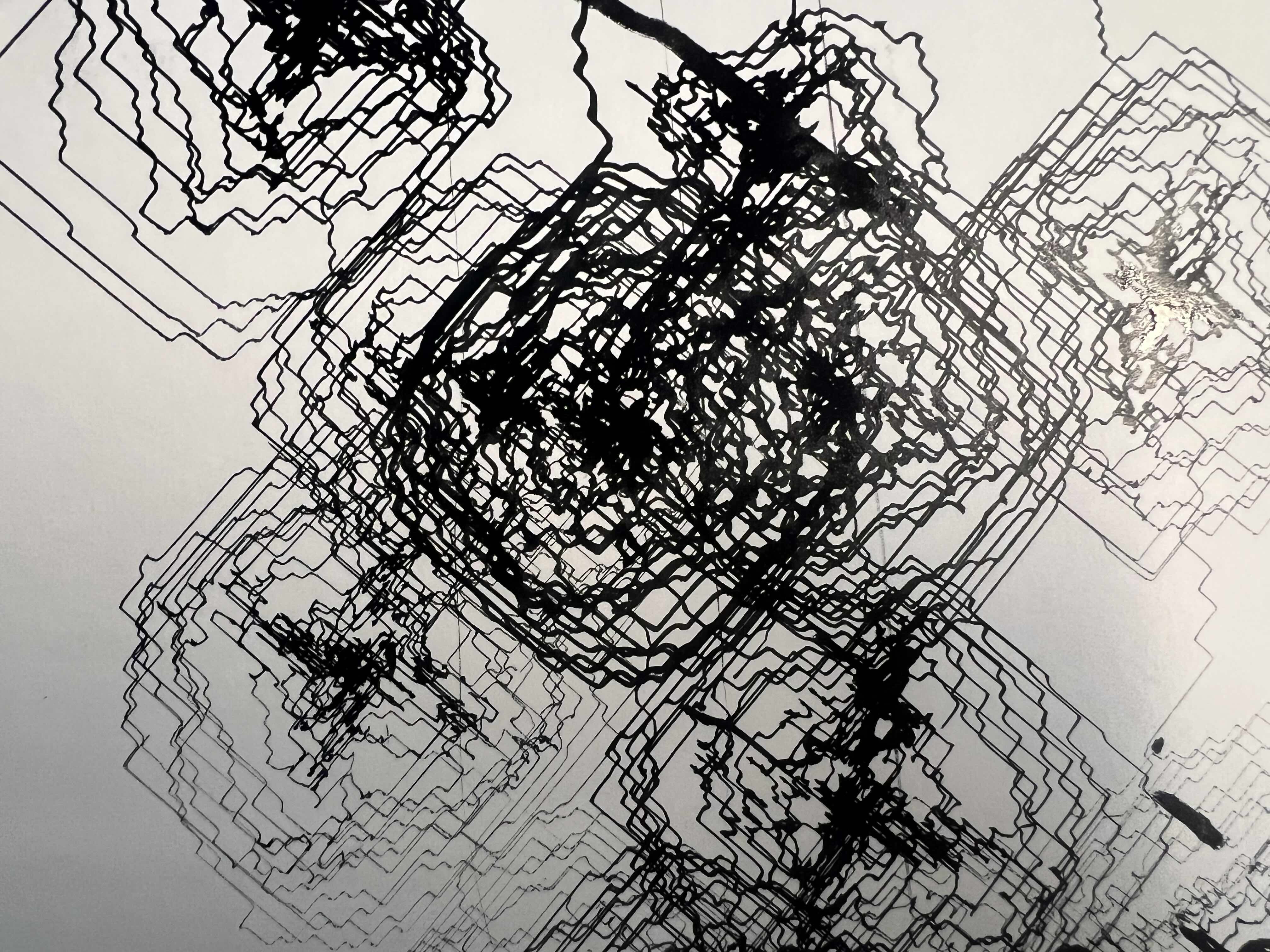
The synthesizer’s output is mapped to the kinematics, then converted to a circular motion. We implented a change line function where the plotter will go to the next grid and start a new circle.
Result
1st version
Final Version
Reflection
This is a great opportunity to understand how signal flows in the stepdance system, and it’s very interesting to have a unusual input to the stepdance as a starting point to utilize the conecpt of mapping in an artistic way. Also very happy to use the plotter as a medium not just focused on drawing specific shapes but on the process of drawing.
If given more time, what we would improve is, first, as we realized in the presentation, the range of the signal has exceeded the resolution of the system, and that’s why we’re not getting as much continuous lines as before we made the movement circular. We could calibrate the voltage and make the result less like an on/off switch. Secondly we realized the interface right now, which is directly manipulating a synthesizer is not the most user-friendly one and it’s hard to have some that does not know how to use this specific synthesizer to be confident enough to try it out.